(For your reference)
Functions:
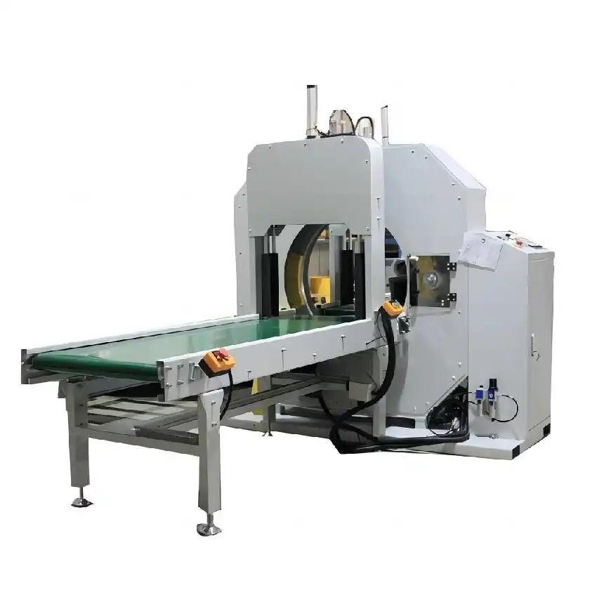
This is an automatic wrapping machine specialized in horizontal shapes such as pipe, sheet, door, floorboard, aluminum profile. The wrapped package is well-protected, sealed and make items tidy. The machine can be connected to the packing line for automatic wrapping.
Installation:
The machine shall be mounted on the flat and hard ground, where the ground load should be more than 1 ton/m2.
Wrapping Station:

- Ring and double-rub wheel devices make operation safe stable and energetic.
- Friction between driving wheels and ring is adjustable.
- Speed of the ring is adjustable by inverter.
- Soft start and start.
- Wrapping position reset.
- Packing material tension could be adjusted.
- Widely packing material adopted by material frame.
- Protect guardrail for safety operation.
- Overlapping is adjustable from 10%-90%
Conveyor :

- Conveyor for protecting the surface of the product
- Automatic entrance conveyor system and outlet conveyor system.
- Conveyor adjustment function.
- Conveyors drive by motor with gearbox.
- Speed of the conveyors is adjustable by inverter.
PLC control system:

- PLC and program make the machine able to do automatic wrapping according to your packing goal.
- Photocell sensor is adapted for setting packing position.
- Indicator alarms automatically when trouble occurs. Trouble can be shown automatically.
- Separate control panel makes operation & maintenance easily.
- Interface operation.
Automatic cutter and feeder(mechanical hand):
- Automatic
- Automatic material feeding system.
- Automatic material cutting.

Special automatic press down device
- It is forholding the package avoid shaking in wrapping.
- Cylinder for press
- Special soft material for preventing scratch and deformation on the product’s surface
Technical parameter:
- Bar package: Width:600mm Height:50mm L:≥1200mm
- Weight:7-25kg
- In feeding conveyorlength: 1000mm with motor
- Out feeding conveyorlength: 1000mm with motor
- Speed: 6~12m/min
- Ring speed: 20-100r/min
- Wrapping speed:5-18m/min
- Power output: about 5kw
- Power voltage: 230v,1 50Hz
- Packing material:Stretch film
- OD:100-200mm Width:150mm ID:50mm
Guarantee value:
- Ring speed: 20-100r/min
- Wrapping effect: Product surfaceis smooth and even.
- Workinghours of the machine
Effective working hour per year:7200h
- Environmental protection:
Noise control of the equipment environment:Must meet with the national requirements for noise control.
- Emission standard
Emission of the waste gas and waste water meet with national requirements.
List of Main parts
| Description | Brand |
| PLC | Siemens |
| Touch Screen(optional) | Siemens |
| Frequency Converters | Siemens |
| Motor | DONGLI/JIEMAI |
| Sensor | Autonics |
| Switch | Schneider |
| Contactor | Schneider |
Scope of supply
| No. | Items | quantity |
| 1 | Wrapping station of the machine | 1set for each |
| 2 | Film frame release device etc. | 1set for each |
| 3 | Electrical cabinet, guardrail etc. | 1set for each |
| 4 | Manual and spare parts | 1set for each |
| 5 | 1m conveyors | 2sets for each |
| 6 | special press down device | 2sets for each |
Switching Cabinets
The electrical devices are installed on mounting plates in closed cabinets, protection degree IP20, designed in form 1 based on EN 60439-1. Each cabinet has a designation label on the door with the appropriate location indicator.
Cabinets with the following dimensions are mainly used:
Width: 800 or 1,200 mm, depth: 600 mm, height: 2200 mm, base 200mm
The switching cabinets are installed in a switching cabinet row.
For transport the cabinet system can be separated into shipping units with a maximum width of 3600 mm.
The subdivision of the individual cabinets is made according to their respective functions:
- Feed
- Control voltage generation, auxiliary drive
- Main drive
- Control
Cooling of the Switch gear
By fans cooling
Lighting of the Switch gear
Lighting for the switchgear is provided by a lamp combination with a 230V outlet built into every other switching cabinet.
Safety Coverings
The used components are protected against accidental contact. Additional endanger components under voltage are covered with transparent covers and warning labels in all transformers, fuses, breakers and copper tracks, etc.
Wiring
The wiring is flexible for all control circuits and lies in covered cable conduits. Attention is given that these cable conduits are filled only up to 70% with wires. The wire color codes and diameters conform to EN 60204.
Terminal Strips
The terminal strips are mounted approximately 250 mm from the lower edge of the switching cabinets.
The terminal strips have labels showing their respective terminal strip number. Each individual terminal is given a terminal number corresponding to the wiring diagram.
Cable stop bars are installed to prevent excessive tension on the outgoing cables.
Identification labels
Each device in the switching cabinet is provided with an adhesive label indicating the designation of the module in the wiring diagram.
Wire Identification
Identification of the individual wires is necessary for the internal wiring in the switching cabinets.
The identification of the incoming and outgoing cables and lines is designed in such a way that they can always be read without detaching the connections or removing the cable stop clamps. The individual wires of a cable can be identified by the terminal number of the connection point. The cable can be identified by its cable number.
Internet assistance unit
Not applicable
Motor drives
For the motors, where we use three-phase asynchronous motors, the basic specifications of the drives is :
Wide range of adjustable speeds
Speed to zero without reduction of the torque
External air-cooling fans
Durable
Transmitter for registering the motor speed
Terminal box for connecting of power cables
AUTOMATIZATION CONFIGURATION
Plant Control
The complete plant will be controlled through manual input on dedicate remote/local control desk and foot switch.
Visualization System
The monitoring of the system will be realized with the software WinCC and will be installed by using the following operator panels:
Machine cabling
The machine cabling conforms to effective regulations. The cables are laid in conduits in the concrete foundation of the line.
When exposed and in hazardous positions, the cables are placed in hoses in the top of the concrete.
The existing termination switches, magnetic valves are connected directly to the bus modules installed in the terminal boxes/substations.
Power cables
Direct cabling is between the individual motors and the wiring cabinets. Regulated drives with frequency inverter with shielded cables.
PLANNING, DOCUMENTATION
Generation of the following documents:
- Wiring diagram in CAD system
- Terminal diagram
- Control panel diagram
Safety system
- Safety guards and covers for single machine and pits
- Under the Guarantee of the Supplier, the line will be supplied in full conformity with the Chinese safety rule regulation.
- Regarding the safety will be installed in the control board a safety
- All drivers of the main motors must be safety enable
- Complete safety guards for the area and CE declaration forms will be supplied by the Customer according to the local laws.
Commissioning materials
The Seller has to provide all necessary material (a part the listed in the exclusion list if any) in order to fulfill the performances and all needs.
INSTALLATION AND TRAINING
- The Seller will supply the Supervision service as per necessary time and presence with a minimum number of days.
- Man presence by the Seller technician
- The Buyer will provide main power working under Seller technicians supervision
- The Seller has to provide at least 1 month in advance of the foreseen starting installation date a list of necessary stuff for installation specifying the type, load, and schedule of using time.
- The Seller has to provide at least 1 month in advance of the foreseen starting installation date a complete instruction report with eventual adjustment, special arrangement and guideline for machinery transportation inside building and charge on foundation plant.
- According to the Seller experience below the foreseen main power days for erection, commissioning and start-up provided by Buyer.